/projects
Homemade Simulation Tools

Updates
Overview
This page will collect the homemade simulation tools built around the engine work: what each tool is for, what assumptions it makes, and how it supports design decisions.
In several of the projects listed on this page, I needed to run fairly advanced engine simulations. One of the biggest challenges was software access. Some industry-grade tools are either very expensive, limited by trial periods, or require add-ons that I did not have access to. That bottleneck became a recurring issue throughout the project, but it also pushed me to find better workarounds and build a stronger understanding of the subject along the way.
At first, I tried creating small Python tools to help fill the gaps. Some of those scripts were quick utilities, but the software featured here became much more involved. These tools went through many revisions and slowly turned into dedicated workflows for organizing data, preparing simulation inputs, checking results, and reducing the amount of manual work required between design changes. A major turning point was finding EngMod2T, an engine simulation program developed by Neels van Niekerk. EngMod2T became a very helpful middle ground: accessible enough for this project, but still powerful enough to support serious two-stroke simulation work. It helped move the project forward much faster and gave me a practical way to test ideas that would have been difficult to evaluate otherwise. I would strongly recommend it to hobbyists, students, or anyone trying to better understand and develop two-stroke engines.
I also looked into the idea of building my own simple engine solver, but that quickly became much more involved than I was ready to take on at the time. Long-term, developing an open-source engine simulation tool is still a goal of mine. I think tools like that could help other students and independent builders avoid some of the same access problems and workarounds that come with relying only on industry-grade software.
The project featured below is my most recent and in-depth project yet; above in the update section are more tools that are an interesting share.
Rotary Exhaust Valve Designer for EngMod2T.
To better understand the objective of this project, it might be advisable to read through the core engine design project. It is assumed that the reader knows the objective from here.
As discussed, I need to find a way to implement a Rotary Exhaust Valve that is downstream of the exhaust port inside of EngMod2T. The program package does not currently offer such an architecture, so some manipulation tactics must be created. EngMod2T does, however, offer a poppet exhaust valve with custom lift timing. This can be used to create a faux REV poppet for the engine. Initial steps to do this were actually supplied by Neels himself, and I took the initial instructions a bit further into a quick and easy visualizer.
This project was completely developed using C/C++ and ImGUI and is an addition of an Excel extractor for EngMod2T output files. C++ is likely overkill for such an application but was used simply because that's the language I know best and have the most experience with.
Intent and Core Process
This project intends to develop the timing curve of the REV based on physical geometry and engine geometry. Then, once designed, the software will generate an equivalent lift profile and valve geometry that is then exportable to EngMod2T and features options to directly inject into a current project file. This allows very low downtime between simulations when changing REV timing characteristics.
Project Importing
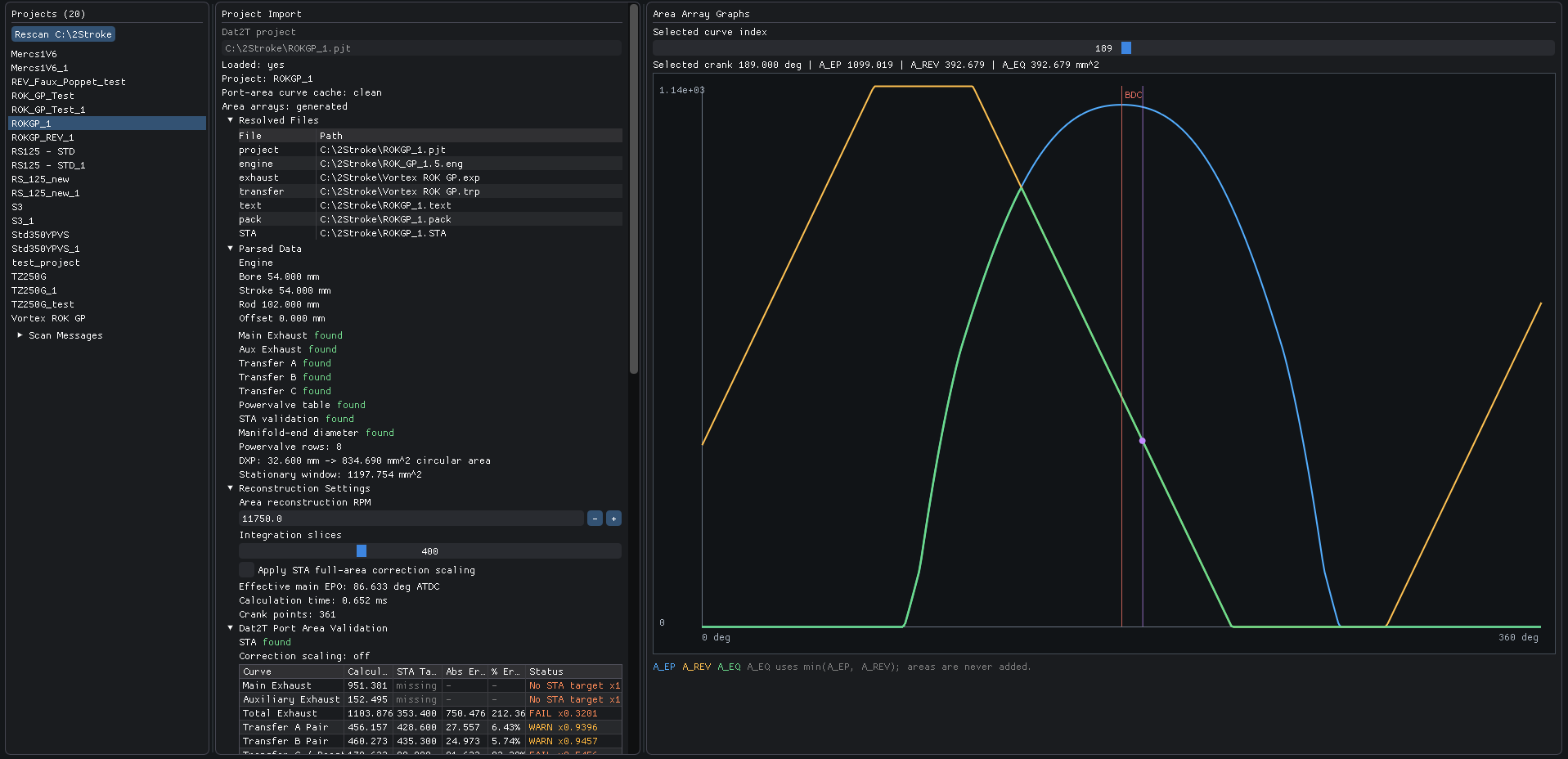
The REV Designer’s project importing process is built around finding and reading Dat2T / EngMod2T project files so the rotary exhaust valve model can be compared against real engine-port information. When the Project Importer tab is opened, the software scans the project folder, which is always C:\2Stroke, and looks for project index files such as .pjt. Once a project is selected, the importer tries to resolve the related engine, exhaust, transfer, text summary, pack, and static-area files that belong to that project. It does this in a few ways:
- by reading file references from the project file,
- by checking nearby files with matching names,
- by handling file extensions case-insensitively, and by using Dat2T’s expected subsystem order when some references are written without full extensions.
This is important because real simulation project folders are not always perfectly organized, so the importer is designed to recover as much useful information as possible instead of failing immediately. This system has worked for my REV design project but sometimes fails at other engine models.
After the files are found, the importer extracts the values needed to rebuild the exhaust and transfer area behavior in the REV Designer. It reads engine geometry such as bore, stroke, and rod length, then pulls exhaust-port details such as opening angle, full-open angle, window count, widths, radii, and manifold-end diameter. It also checks auxiliary exhaust and transfer-port data when available. It also finds static-area values that can be used to validate or scale the reconstructed curves.
In simple terms, the importer turns a scattered Dat2T project folder into structured information the REV Designer can use. From there, the software can calculate the effective exhaust restriction by comparing the imported port area against the REV opening area at each crank angle.
Project Exporting
The export process is built around taking the finished equivalent lift curve and turning it into files that can be used by the EngMod2T / Dat2T workflow. Once the user has generated the equivalent poppet result, the software can save that lift profile as a .C4T file. This file contains the crank-angle and lift data in the simple format expected by the downstream valve-profile workflow. The exporter also validates the saved file so the user can confirm that the angle range, lift values, line endings, and basic formatting are suitable.
Beyond saving the lift curve by itself, the software also includes a direct Dat2T / EngMod2T project injection path. In that workflow, the user selects a target Dat2T project, and the REV Designer generates the needed faux-poppet exhaust files around the equivalent lift curve. It can write a new .exp exhaust subsystem file and a matching .c4t lift-profile file, then update the selected project so the generated exhaust file is connected into the project structure. This process has been extremely handy for this project.
REV Designer Tab
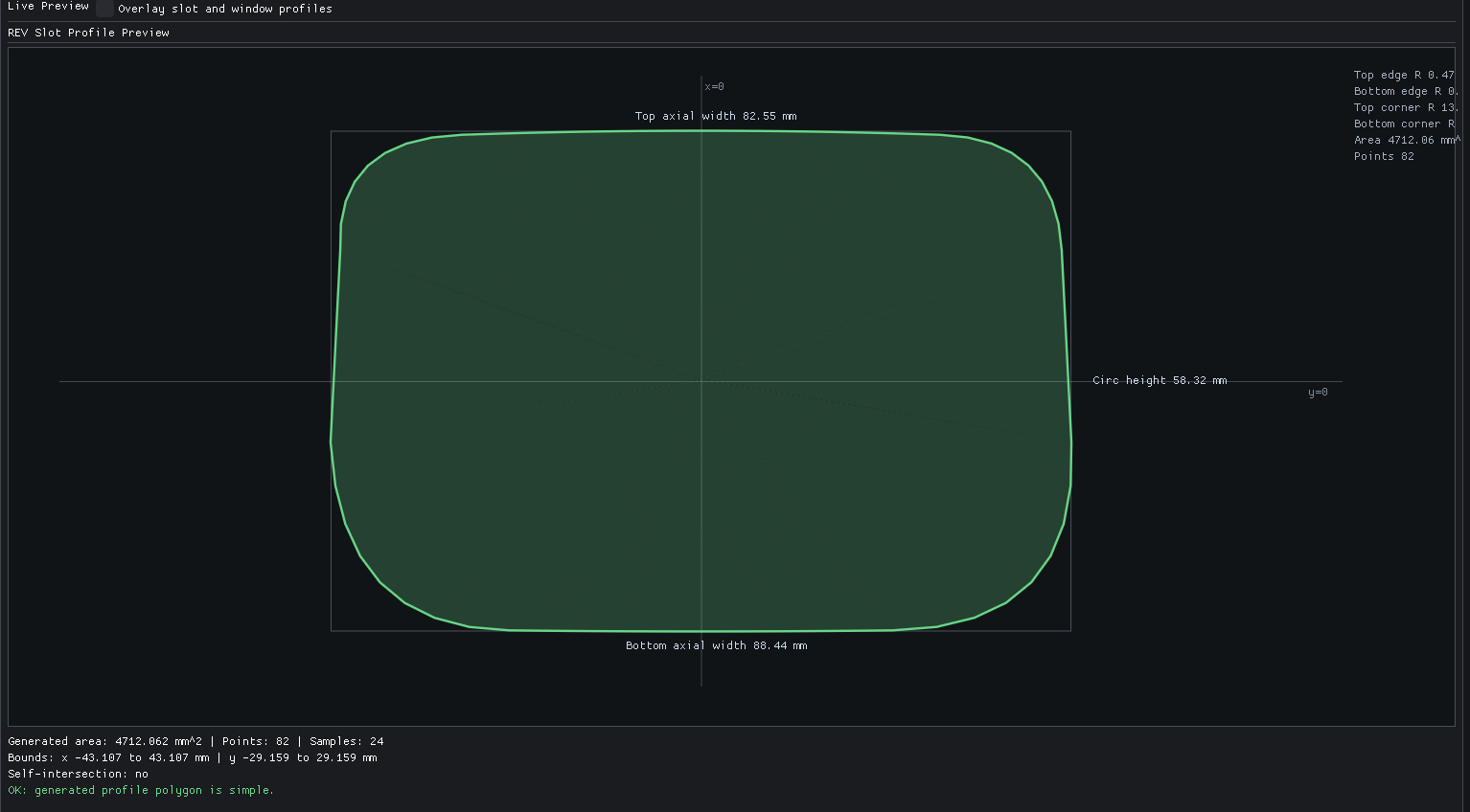
The REV Designer itself is a focused workspace for defining the physical layout and motion of a rotary exhaust valve. The user starts by setting the main geometry: rotor diameter, rotor length, slot size, stationary-window size, and has the option to design detailed slot/window profiles. Internally, the rotor is treated as a cylinder that can be “unwrapped” into a flat surface, which makes the valve easier to visualize and measure. In that flattened view, the horizontal direction represents distance around the rotor circumference, and the vertical direction represents distance along the rotor length. This lets the software move between a real cylindrical valve and a simple flat layout that is easier to inspect and calculate.
Timing is controlled by the relationship between crank angle and rotary-valve angle. The user can adjust the drive ratio, phase offset, and rotation direction to control how quickly the valve moves and where it lines up during the engine cycle. The valve angle is described as $\(\theta_{REV} = \phi + d(r\theta_{crank})\)$, where $\(\phi\)$ is the phase offset,$ \(d\)$ is direction, $\(r\)$ is the drive ratio, and \(\theta_{crank}\) is the crank angle. That valve angle is then converted into a physical shift around the rotor surface, letting the software show where the moving slot sits relative to the fixed exhaust window at each point in the cycle.
The key equivalent behavior in the REV Designer comes from comparing the valve opening against the engine’s exhaust-port opening. The software treats the piston-controlled exhaust port and the rotary exhaust valve as two restrictions in the same flow path, so the effective available area is based on whichever one is smaller at that crank angle. This is simply shown as $\(A_{EQ}(\theta) = \min(A_{EP}(\theta), A_{REV}(\theta))\)$. This gives a practical way to see whether the exhaust port or the rotary valve is controlling flow at each moment. The result is not just a static geometry measurement; it is a timing-aware picture of how the valve design behaves throughout the engine cycle.
Calculating Lift Profiles
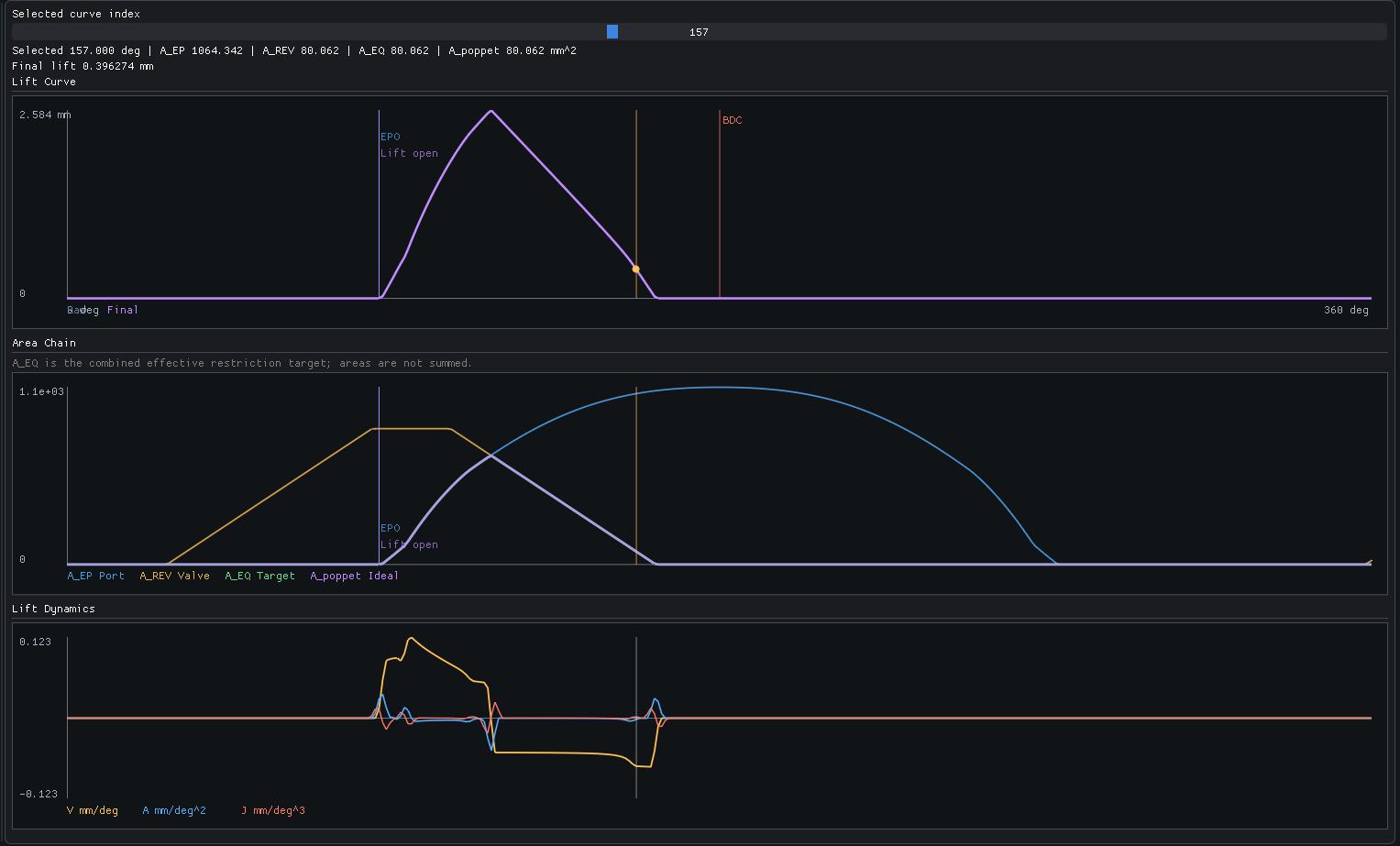
Once the REV Designer has a finished timing and area profile, it prepares that information for export by turning the rotary-valve behavior into a poppet-style representation. The important idea is that the rotary valve does not physically move like a poppet valve, but the software can describe its effect in a form that EngMod2T can understand. The REV Designer takes the final equivalent area curve, $\(A_{EQ}(\theta)\)$, and uses it as the target shape for an exported valve profile. Instead of exporting the rotary slot motion directly, it creates a lift profile that opens and closes over crank angle in a way that represents the same controlled exhaust-area behavior.
From there, the software prepares the supporting valve geometry needed for that lift profile to make sense inside the downstream project files. The user can define or generate the effective curtain diameter, max lift target, and related faux-poppet settings, and the software packages those values with the exported curve. The lift curve is the motion data, while the generated valve geometry tells the simulation software what kind of equivalent valve that motion belongs to. This is how the REV Designer bridges the gap between a rotary exhaust valve concept and the poppet-valve style inputs expected by the existing simulation workflow.
The software also has options to include generated discharge coefficient plots. This will be an incredibly useful feature when CFD or flow testing is available. This will enhance the fidelity of the faux poppet system and create a much more accurate simulated result in the future.
Visualizing Tools
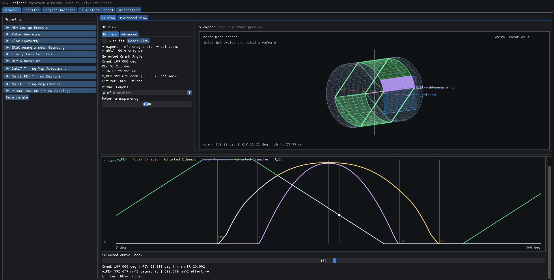
The REV Designer includes both a 3D viewer and a flat plotting system. This was not 100% necessary but has proved to be very helpful when using the tool. I believe that being able to visualize numbers in any way is important to developing a better understanding. As said earlier, the Dear ImGUI library is used for this along with Direct3D. The 3D viewer shows the rotary valve as a cylindrical rotor with a slot, stationary window, and active overlap area drawn on the surface. This gives a clear visual reference for how the moving slot lines up with the fixed exhaust window as the crank angle changes. The user can rotate, zoom, and inspect the view while stepping through the engine cycle, which makes it much easier to see whether the timing and geometry are behaving as intended.
The plotting side shows the same behavior as curves over crank angle. The software can display the rotary valve open area, the imported or reconstructed exhaust-port area, and the final equivalent area on the same graph. This makes it easy to see where the piston port is controlling flow, where the REV is controlling flow, and how the two restrictions interact across the cycle.